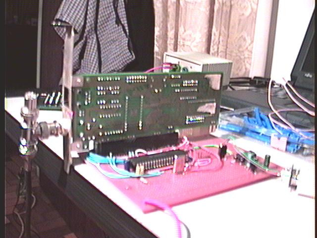
First, let's get a common board to start the mounting. IMHO, the
*hardest* phase of this project was cutting an oldie XT mainboard to get
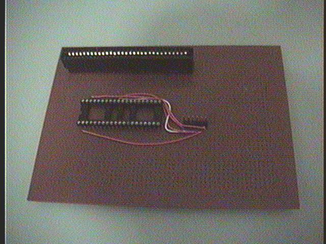
a ISA Slot.

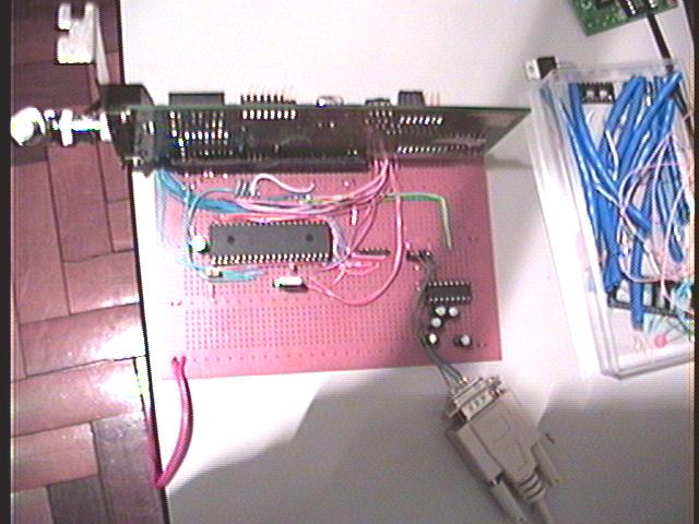
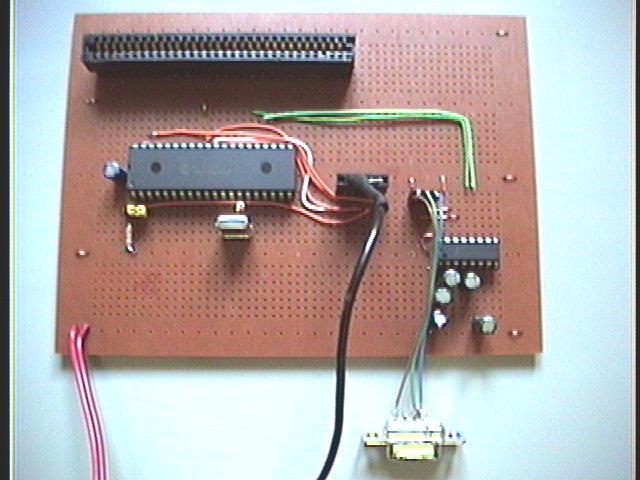
This is the board used for this picnic assembly. The connections are
like a proto' board.
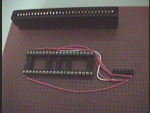
Well, this is the ICSP (In Circuit Serial Programming) System of this
circuit. The idea here is to separe the wires function by colors - so
all orange wires are for programming interface.
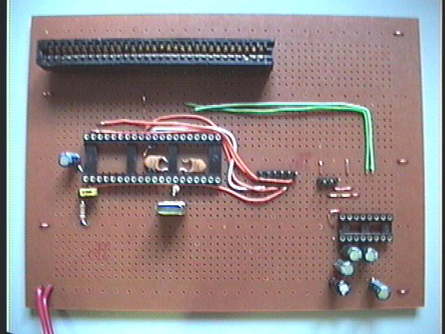
Then, lets put the minimal to the
system work and talk to the external world. A crystal to give the PIC
its clock. A Reset circuit, and a yellow jumper to put the PIC in
programming or running mode, or even just resetting the unit. At the
bottom we have the serial line interface with a PC. The green wires are
for serial data.

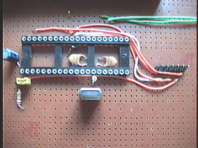
A closer look at serial interface circuit. It uses a MAX232 to convert
RS232 levels to PIC and the opposite. The 3 pin connector is GND, TX
and RX to be connected to a PC. At the left we can see the ICSP
interface.
Finally, the basic setup to make a PIC work.
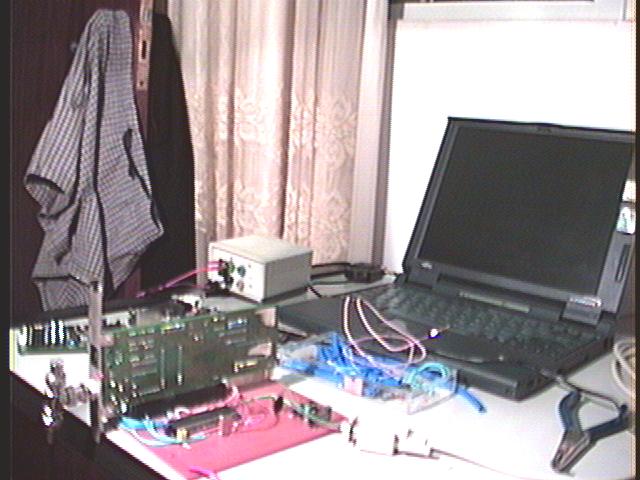
Now, we can connect the cables.

And attach the programmer, to download into the PIC the firmware.
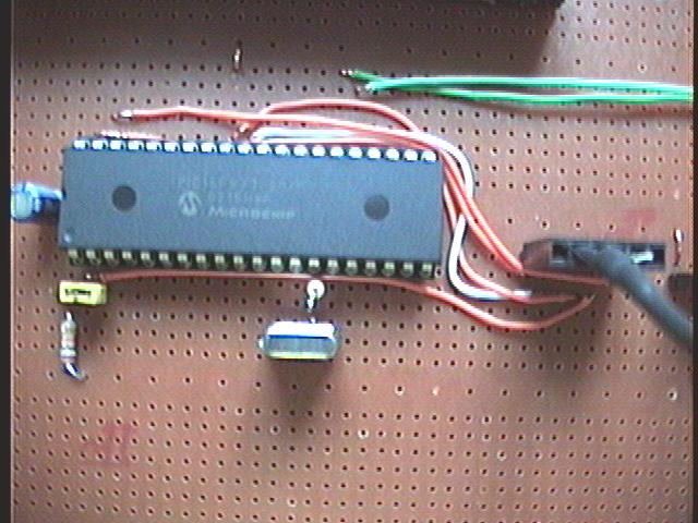
A closer look to our main device - The PIC 16F877
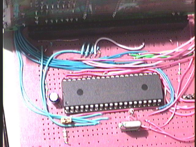
Now, the ISA connections:
8 Blue wires: D0-D7 - DATA
10 Brown wires: A0-A10 - Adressing the board
White wire: Interrupt (IRQ4)
Other Blue wires: Signaling
Data and adress lines.